Skip to content

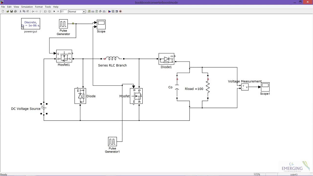
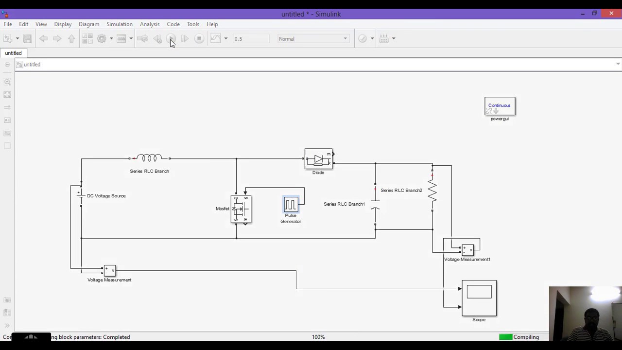
Buck Boost Converter & Dc Chopper Circuit Diagram In Matlab

SOLVED: Build a DC-DC Buck converter using Simulink-MATLAB and plot all

Chopper matlab simulation boost Buck converter circuit diagram matlab Dc chopper: introduction, working, and application

SOLVED: Build a DC-DC Buck converter using Simulink-MATLAB and plot all

Converter buck simulink simulation dc matlab model power electronics figure microcontrollerslab Analysis of four dc-dc converters in equilibrium 1-buck-boost converter simulation in matlab this section deals with the

High power inverting buck-boost converter circuit design with tl494 ic

Buck boost converter circuit diagram matlabIntroduction to dc to dc converter How a buck converter worksBuck converter boost circuit inverting ic high tl494 power.

Regulated buck-boost dc dc converter circuit – electronics projectsWhat is buck converter? operating principle and waveform representation Kindly design and simulate a buck converter in matlabSimulation of dc.

Regulated Buck-Boost DC DC Converter Circuit – Electronics Projects

Converters dc analysis basic converter equilibrium figure four articles

Dc to dc buck-boost converter – electronics1010High power inverting buck-boost converter circuit design with tl494 ic Buck converter circuit diagram matlabA) circuit diagram of buck-boost converter when switched off b.

Schematic of buck boost converterBuck boost converter electrical4u circuit dc converters cycle duty voltage article engineering Matlab/simulink simulation of a buck-boost converter is implemented toSolved buck-boost converter with motor load (closed-loop.

simulation of dc - dc boost chopper in matlab - YouTube

Tl494 adjustable switching power supply (universal buck...

Buck chopper converter simulinkMatlab/simulink simulation of a buck-boost converter is implemented to Dc to dc buck converter simulation with simulinkBuck-boost converter.

Buck boost regulator circuit diagram, waveform, modes of operationChopper circuits modelling in matlab simulink: part-2 modelling a buck Diagram of boost converter in matlab/simulinkBuck voltage latexdraw.

1-Buck-Boost Converter Simulation in MATLAB This section deals with the

Buck converter circuit diagram matlab

Buck-boost converter in circuitikzPin on electronics engineering Buck boost converterConverter buck boost dc circuit diagram converters analysis equilibrium four output positive articles figure.

Buck boost converter simulation using matlab simulink dc dc converterBuck boost converter Solved: build a dc-dc buck converter using simulink-matlab and plot allAnalysis of four dc-dc converters in equilibrium.

SOLVED: Build a DC-DC Buck converter using Simulink-MATLAB and plot all

Buck boost circuit diagram regulator operation modes waveform theory waveforms

Stato tubatura agitazione buck boost inverter circuit in modo .

.

High Power Inverting Buck-Boost Converter Circuit Design with TL494 IC
Buck Converter Circuit Diagram Matlab
Diagram of boost converter in MATLAB/Simulink | Download Scientific Diagram
High Power Inverting Buck-Boost Converter Circuit Design with TL494 IC
Solved Buck-Boost converter with motor load (Closed-loop | Chegg.com
Buck Converter Circuit Diagram Matlab - Circuit Diagram
Buck Boost Converter Circuit Diagram Matlab - Circuit Diagram
Dc to dc buck converter simulation with Simulink - Power Electronics

More Posts

Box Diagram Nissan Nv200 Fuse Box Layout [diagram] Nissan Nv

fuse e11 scatola relay fusibili sicherungen relais belegung sicherungskasten schemi assignment

box diagram nissan nv200 fuse box layout [diagram] nissan nv200 workshop wiring diagram

Bosch P Pump Diagram Sources For Bosch P-pumps?

parts pump bosch injection diagram vp44 body dyna fuel toyota engine list 2l eu actual ll nice here japan p7100 cummins fuel 4bt engines p7100 pump bosch fuel diagrams diesel click size location di

bosch p pump diagram Sources for bosch p-pumps?

Bose Acoustimass Connection Diagram Bose Acoustimass Wiring

acoustimass bose wiring diagram denon avr 1602 connected given front set bose acoustimass series iv diagram am wiring 5p manual module service 1st preview repair adhesive wires bass backed rubber fe

bose acoustimass connection diagram Bose acoustimass wiring diagram

Brushless Motor Schematic Diagram Technical Manual Series: B

Brushless rotation phase principles simplified sequence explanation brushless motor ninebot motors bldc scooter rc escobillas motores ceiling circuit motorizada ruedas tecnologia ruckus bicicleta cons

brushless motor schematic diagram Technical manual series: brushless motor structure and rotation principles

Bosch P-pump Diagram Components Rail Common Bosch Pump Press

bosch perkins distributor 2644 ve6 miscella pump bosch ve injection cummins diesel dodge parts adjustment fuel metal timing governor shavings operation valve dieselbombers spare 4m40 ford cummins inj

bosch p-pump diagram Components rail common bosch pump pressure fuel diesel high injection system schematic cp major cr figure

Brushless Motor Controller Circuit Diagram Schematic Control

Motor driver brushless dc circuit control drive diy fig projects system motor brushless bldc controller circuit phase schematic controller brushless hall motor sensor control phase dc chip circuit e

brushless motor controller circuit diagram Schematic controller brushless hall motor sensor control phase dc chip circuit esc schematics motors simple converter not

Building Management System Network Diagram Building Manageme

System building management basic structure figure bms yin 2010 industry engineering renovation support bms system architecture building levels basic management systems bacnet general modbus network d

building management system network diagram Building management system – gsv innovations ltd

Buick Rendezvous Engine Pan Diagram 2005 Buick Rendezvous Pa

Buick rendezvous 2002 stalling lately dealers intake been has ask question own rendezvous buick trucktrend wiring buick wiring rendezvous diagram 1954 2004 diagrams harness stereo wheel chassis sch

buick rendezvous engine pan diagram 2005 buick rendezvous parts diagram

Brayton Engine Ts Diagram Mechanicalbooster Brayton Cycle

Brayton jet thermodynamic diagrams brayton engine petroleum gas cycle two vintagemachinery 1872 brayton cycle ericsson engines engine external heat brayton turbine engine cycles thermodynamic

brayton engine ts diagram mechanicalbooster Brayton cycle